


NXP Semiconductors TEA2017DB1580 240W Demo Board

NXP Semiconductors TEA2017DB1580 240W Demo Board is a resonant power supply reference design based on the TEA2017AAT Digital Configurable LLC and Multimode PFC Controller, paired with the TEA2095T Dual LLC Resonant SR Controller. The TEA2017AAT can be configured to operate in DCM/QR, CCM fixed frequency, or multimode, which supports all operating modes to optimize the PFC efficiency. The TEA2095T incorporates an adaptive gate drive method to save the maximum amount of energy at any load. To increase efficiency, the TEA2095T can operate at 90μA with a -25mV regulation level, which optimizes functionality for use with low-ohmic MOSFETs.
The NXP Semiconductors TEA2017DB1580 240W Demo Board can operate at a mains input voltage between 90V (RMS) and 264V (RMS; universal mains). The Demo Board features three subcircuits:
- A DCM/QR/CCM-type PFC converter
- A resonant LLC-type HBC converter
- An SR resonant LLC-type output stage
The purpose of the Demo Board is to demonstrate the operation of the TEA2017 PFC + LLC controller and the TEA2025T Synchronous Rectifier in a single output voltage power supply, which includes the operation modes in a typical design. The performance passes general standards, including the EuP lot6 requirements.
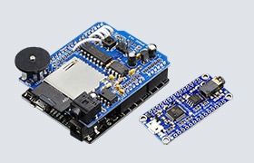
The TEA2017DB1580 Demo Board can be connected to a PC using the RDK01DB1563 USB-I2C Programming Interface. The Ringo development software provides a graphical user interface (GUI) to set the TEA2017AAT Controller parameters.
Features
- TEA2017AAT Digital Configurable LLC and Multimode PFC Controller
- TEA2095T Dual LLC Resonant SR Controller
- 90V to 264V input voltage range
- 12V, 20 output voltage
- Excellent PF and THD performance
- Integrated X-capacitor discharge without additional external components
- Power good function
- Digitally configurable
- Synchronous rectifier at the secondary side
- High efficiency from low load to high load
- Overpower protection (OPP)
- Brown-in/brown-out protection
- Overcurrent protection (OCP)
- Capacitive mode regulation (CMR)
- Accurate overvoltage protection (OVP)
- Inrush current protection (ICP)
- Supply under-voltage protection (UVP)
- Internal and external overtemperature protection (OTP)
- Independently configurable levels and timers
- Protections can independently be set to be latched, safe restart, or latched after several attempts to restart
Specifications
- 90V (RMS) to 264V (RMS) input voltage (VI)
- 47Hz to 63Hz input frequency (fI)
- <100W no load input power (Pi (no load))
- <450W standby power consumption (Pi (load-250mW))
- 12V output power (VO)
- 0A to 20A output current (IO)
- 24A maximum output power (IO (max))
- 30A maximum peak output current (Io (peak) max)
- >10ms hold time @ 115V/60Hz (thold)
- <0.5s start time @ 115V/60Hz (tstart)
- ≥89% efficiency (η)
- 168mm x 80mm PCB
Required Equipment
- RDK01DB1563 USB-I2C Programming Interface
- AC mains source
- Power analyzer (optional)
- Electronic load (20A, 12V minimum)
- Oscilloscope for observing operation behavior
- Windows PC with USB for parameter modifications
Supported Devices

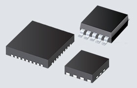
NXP Semiconductors TEA2095T GreenChip Dual SR Controller
Dedicated controller IC for synchronous rectification on the secondary side of resonant converters.

NXP Semiconductors TEA2017AAT LLC & Multimode PFC Controller
A digital configurable LLC and PFC combo controller for high-efficiency resonant power supplies.

NXP Semiconductors TEA6017AT LLC & PFC Combo Controller
Implements the LLC & PFC controller functionality required for high-efficiency resonant supplies.
Related Development Tools

NXP Semiconductors RDK01DB1563 USB-I2C Programming Interface
Enables programming of the parameters of the TEA2016 Digital LLC+PFC Combo Controller.
Setup Example
