Selecting the Optimal Low Noise Amplifier for Your Application
By Alan Ake, Skyworks Solutions, Inc
The purpose of this article is to help designers of receiver products select the optimal low noise amplifier (LNA) for their particular application. First, we will take a look at a typical receiver architecture and the LNAs role within it. From there, the article will offer some practical tips regarding things to consider when selecting a specific LNA device regarding process, biasing and cost. Finally, we will take a look forward to a device which will serve as the foundation for a new generation of state-of-the art LNAs from Skyworks.
The LNA from a System Perspective
An LNA is simply an amplifier with sufficient gain and suitable low noise figure (NF) which allows it to reduce the cascaded NF of the receiver to an acceptable level. However, before we go further, let us step back and consider a generic receiver (Rx) architecture to get an idea of the role played by the LNA.
Equation 1: The Friis Cascaded Noise Formula.
An understanding of this equation lies at the heart of the LNA selection process for any application. It shows how the gain and noise figures of each receiver stage contribute to the total cascaded NF. Clearly, high LNA gain works to reduce the cascaded NF but there is an issue. LNA gain directly degrades the receiver linearity. The limiting stage in terms of linearity is usually the first down converting mixer and, for a given input signal level, higher LNA gain results in higher power applied to the mixer input. The NF improvements of increasing LNA gain must be balanced against the linearity degradation caused by this gain.
To see the LNA gain contribution to cascaded NF more clearly, imagine three receivers which have the following cascaded NF characteristics:
Receiver 1: Cascaded NF of 12 dB. Example: High-performance discrete architecture receiver such as that used in cellular infrastructure.
Receiver 2: Cascaded NF of 8 dB. Example: Integrated CMOS transceiver with a relatively poor cascaded NF.
Receiver 3: Cascaded NF of 4 dB. Example: High performance transceiver which already has an integrated LNA.
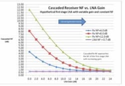
Now, imagine that we are able to add a hypothetical LNA to the input of each of these three receivers. This LNA has a constant NF of 0.7 dB and a variable gain from 0 to 24 dB.Figure 2 shows the effect of increasing LNA gain on the resulting cascaded NF.

Figure 1: Plot of Cascaded NF vs. LNA Gain
Figure 1 shows that there is an LNA gain level beyond which the NF improvements diminish. These curves enable the designer to specify an LNA gain and NF which represent an intelligent compromise between improving NF and degrading receiver linearity. A key point here is that any LNA can only improve sensitivity by a finite amount equal to the difference between its NF and the NF of the receiver cascade with no LNA present. In the case of the receiver with a 4 dB NF, with infinite LNA gain, the improvement is only 3.3 dB. With only 12 dB LNA gain, the improvement would still be around 3 dB.
General Device Considerations
Process: E-mode pHEMT is the dominant technology for the lowest NF LNA and these modern processes have led to lower cost, super low noise, high linearity devices which can be used anywhere from high volume commercial applications to the highest performance infrastructure applications. A key advantage of the E-mode pHEMT is that it provides optimal performance from a single positive supply voltage.
Bias Voltage and Current: Typically, the gain and NF of modern pHEMT devices is insensitive to supply voltage over the common supply ranges of 2.7 to 6 volts. Higher supply voltage tends to result in a higher compression point for the amplifier while IP3 is usually more a function of device current. Look for devices having bias control pins which allow quiescent current to be set independently from the supply voltage. Having this flexibility in bias voltages and quiescent current allows the device linearity to be adjusted according to the specific application requirements thus maximizing efficiency.
Device Cost: Given today’s high performance, low cost pHEMT, there is little reason from a price perspective for not choosing a pHEMT device. That said, the LNA NF will tend to drive the cost of the device up sharply as the NF drops below about 0.7 dB. Requirements for higher linearity will also tend to increase the device cost often due to the need for larger amplifier die sizes. A clear understanding of the NF and linearity requirements is essential towards finding the most cost-effective solution.
A look ahead to new levels of NF performance:
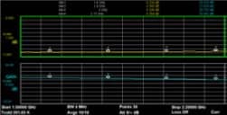
Figure 2 below, shows a preview of Skyworks’ next generation pHEMT device which is now sampling with full production scheduled for fall of 2012. Devices from this product family will allow designers to create LNA modules and receivers with lower NF than ever before.

Figure 2: The SKY67151 next-generation LNA measured NF and Gain data for 1600-2170 MHZ tune.
Conclusion
Selecting an LNA involves achieving the desired cascaded NF while keeping LNA gain to a minimum to preserve the receiver linearity. A key take away is that an LNAs only purpose is to reduce the cascaded receiver NF. Today’s advanced pHEMT devices offer optimal LNA solutions for applications ranging from high volume WLAN and ISM applications up to infrastructure LNA applications requiring the highest levels of performance. Skyworks has a wide range of LNA devices to choose from which allow a designer to accomplish this task for applications from 100 MHz up to 2.7 GHz and beyond.